Friday, February 24, 2017


Wednesday, February 15, 2017
Drafting Speed
Everyone in Auto Cad drafts at a different speed. When you’re watching someone use Auto Cad, especially if you are unfamiliar with the software, you might find yourself amazed at how fast their fingers fly to create a drawing. Conversely, if you've never seen someone that is very quick at using Auto Cad, then you might think that you've reached a plateau and that’s it’s not possible to become faster.
All this talk about finger speed is really a red herring. There are more important factors in someone’s proficiency using Auto Cad than their APM (actions-per-minute). One of them has nothing to do with AutoCAD itself. It’s how familiar are you with what you are drawing. Knowing the subject inside and out is going to produce more accurate drawings faster.
On the technical side of Auto Cad, here are some methods to increase your performance:
1. Minimize repetitive tasks
Example – You need to rotate many blocks simultaneously, use the properties window.
Example – You need to rotate many blocks simultaneously, use the properties window.
2. Know when you need to press keys and when you don’t.
Example – When joining many lines together, the Join command will act exactly like PEdit join if you select a polyline as the first object.
Example – When joining many lines together, the Join command will act exactly like PEdit join if you select a polyline as the first object.
3. Get the vertical product specific to your discipline
Revit, Auto Cad Architecture, Civil 3D, or MEP will make it easier to design. The learning curve might make it more difficult at first, but the investment is well worth it.
Revit, Auto Cad Architecture, Civil 3D, or MEP will make it easier to design. The learning curve might make it more difficult at first, but the investment is well worth it.
4. Use styles efficiently, don’t override
Example – Create a dimension style and set the scale for the style, do not just rely on the DIMSCALE variable. From then on, change the style when working on a detail that’s at a different scale. Even better, put this into a template.
Example – Create a dimension style and set the scale for the style, do not just rely on the DIMSCALE variable. From then on, change the style when working on a detail that’s at a different scale. Even better, put this into a template.
5. Get training
This is especially important if the number of Auto Cad users you interact with is low.
This is especially important if the number of Auto Cad users you interact with is low.
6. Customize
If there is a tool that you use multiple times a day that is not easy to get to, then make it easily accessible. You can use the CUI, LISP, PGP or Macro Recorder to make it easier to access your commands.
If there is a tool that you use multiple times a day that is not easy to get to, then make it easily accessible. You can use the CUI, LISP, PGP or Macro Recorder to make it easier to access your commands.
Monday, February 13, 2017
ABOUT OFFSET COMMAND
Creates concentric circles, parallel lines, and parallel curves.
Find
You can offset an object at a specified distance or through a point. After you offset objects, you can trim and extend them as an efficient method to create drawings containing many parallel lines and curves.
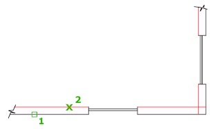
The OFFSET command repeats for convenience. To exit the command, press Enter.
The following prompts are displayed.
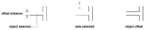
Offset Distance
Creates an object at a specified distance from an existing object.
- Exit
- Exits the OFFSET command.
- Multiple
- Enters the Multiple offset mode, which repeats the offset operation using the current offset distance.
- Undo
- Reverses the previous offset.
Through
Creates an object passing through a specified point.
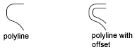
Note: For best results when you offset a polyline with corners, specify the through point near the midpoint of a line segment, not near a corner.

- Exit
- Multiple
- Undo
Erase
Erases the source object after it is offset.
Layer
Determines whether offset objects are created on the current layer or on the layer of the source object.
About Using Object Snaps
Object snaps provide a way to specify precise locations on objects whenever you are prompted for a point within a command.
For example, you can use object snaps to create a line from the center of a circle to the midpoint of another line.
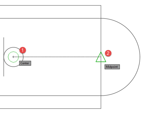
You can specify an object snap whenever you are prompted for a point. By default, a marker and a tooltip are displayed when you move the cursor over an object snap location on an object. This feature, called AutoSnap ™ , provides visual confirmation that indicates which object snap is in effect.
Specify an Object Snap
To specify an object snap at a prompt for a point, you can do one of the following:
- Press Shift and right-click to display the Object Snap shortcut menu
- Right-click and choose an object snap from the Snap Overrides submenu
- Click an object snap button on the Object Snap toolbar
- Enter the name of an object snap
When you specify an object snap at a prompt for a point, the object snap stays in effect only for the next point that you specify. Object snaps work only when you are prompted for a point.
Note: If you want object snaps to ignore hatch objects, use the OSOPTIONS system variable.
Use Running Object Snaps
If you need to use one or more object snaps repeatedly, you can turn on running object snaps, which persist through all subsequent commands. For example, you might set Endpoint, Midpoint, and Center as running object snaps.
- On the status bar, click the Object Snap button or press F3 to turn running object snaps on and off.
- On the status bar, click the down-arrow next to the Object Snap button, and then click the object snaps that you want to persist. Find
Tip: If several running object snaps are turned on, more than one object snap may be eligible at a given location. You can press Tab to cycle through the possibilities before you specify the point.
About Revision Clouds
Revision clouds are polylines that consist of sequential arcs. They are used to call attention to portions of a drawing.
A revision cloud is a polyline of sequential arcs to form a cloud-shaped object. If you review or redline drawings, you can increase your productivity by using the revision cloud feature to highlight your markups.
Create Revision Clouds
You can create a revision cloud by moving the mouse, or you can convert objects, such as a circle, ellipse, polyline, or spline, to a revision cloud. A style is available to make the cloud look as though it was drawn with a calligraphy pen.
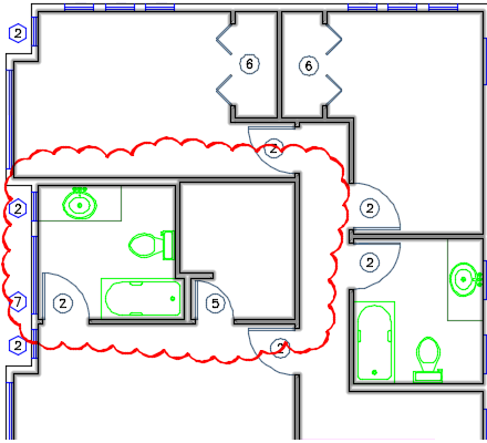
Modify Revision Clouds
Revision clouds offer grip-specific options depending on the grip location and the setting of the REVCLOUDGRIPS system variable.
When REVCLOUDGRIPS system variable is off, you can use the grips to edit the individual arc lengths and chords in a revision cloud. Otherwise, the grips display options to add or remove a vertex, or stretch the revision cloud or its vertex.
solution AutoCAD Freezes when switching layouts
Issue:
When switching between layouts you experience poor performance with AutoCAD 2017.Causes:
Unsupported graphics card.Solution:
Try the following:- Go to the manufacture of the graphics card and download their latest driver available.
- Change DYNMODE from 2 to -2
- Reinstall Direct X -11
- Type GRAPHICSCONFIG and ensure the following are checked:
Smooth line display
Uncompressed Texture.
HOW TO SOLVE FATAL ERROR IN AUTOCAD
Issue:
When starting up AutoCAD, the program crashes with a fatal error.
Causes:
Fatal errors have a variety of causes. They often indicate a corrupt drawing, program corruption, or a problem with the system configuration.
Solution:
There are several ways to troubleshoot the problem:
- Update AutoCAD.
Updates for latest releases are acquired via the Autodesk Desktop App. Right-click its icon down on the status bar next to the time and pick "Check now." You may also download updates through your Autodesk Account (see How to Access Product Updates in Autodesk Accounts). For older products, see Autodesk Downloads.
- Try opening another drawing.
If you can open another drawing, the original drawing may be corrupt and require repair.
See: How to repair corrupt AutoCAD files
- Uninstall any antivirus or desktop locking programs.
These programs can cause errors in AutoCAD, since they prevent the system environment from working.
- Reset AutoCAD to defaults.
See: How to reset AutoCAD to defaults
- Turn off Hardware Acceleration.
See: Starting AutoCAD-based products without hardware video acceleration
- Update your graphics driver.
Install the latest graphics driver from your video card manufacturer or use an AutoCAD-certified driver.
See: How to update your system to the latest certified video driver
- Try logging in under a new Administrator Windows Account.
If you create a new account and can successfully open the drawing, you can either use that account or rebuild the user profile in Windows.
See: How to create a new local administrator Windows user account
- If DisplayLink Core software is installed on your system, try uninstalling it.
- Do a full uninstall and reinstall of AutoCAD.
See: Remove All Products from a Windows System
- Uninstall and reinstall the .NET Framework.
See: How to remove and reinstall the Microsoft .NET Framework
- Uninstall and reinstall Visual C++.
See: How to remove and reinstall Microsoft Visual C++ Runtime Libraries
- Clear the digital signature icons and then uninstall and reinstall the application.
See: FATAL ERROR: Unhandled Access Violation Reading 0x0000 Exception at 4048b9h
- Update AutoCAD.
Updates for latest releases are acquired via the Autodesk Desktop App. Right-click its icon down on the status bar next to the time and pick "Check now." You may also download updates through your Autodesk Account (see How to Access Product Updates in Autodesk Accounts). For older products, see Autodesk Downloads. - Try opening another drawing.
If you can open another drawing, the original drawing may be corrupt and require repair.
See: How to repair corrupt AutoCAD files
- Uninstall any antivirus or desktop locking programs.
These programs can cause errors in AutoCAD, since they prevent the system environment from working. - Reset AutoCAD to defaults.
See: How to reset AutoCAD to defaults - Turn off Hardware Acceleration.
See: Starting AutoCAD-based products without hardware video acceleration - Update your graphics driver.
Install the latest graphics driver from your video card manufacturer or use an AutoCAD-certified driver.
See: How to update your system to the latest certified video driver - Try logging in under a new Administrator Windows Account.
If you create a new account and can successfully open the drawing, you can either use that account or rebuild the user profile in Windows.
See: How to create a new local administrator Windows user account - If DisplayLink Core software is installed on your system, try uninstalling it.
- Do a full uninstall and reinstall of AutoCAD.
See: Remove All Products from a Windows System - Uninstall and reinstall the .NET Framework.
See: How to remove and reinstall the Microsoft .NET Framework - Uninstall and reinstall Visual C++.
See: How to remove and reinstall Microsoft Visual C++ Runtime Libraries - Clear the digital signature icons and then uninstall and reinstall the application.
See: FATAL ERROR: Unhandled Access Violation Reading 0x0000 Exception at 4048b9h
Sunday, February 12, 2017
Friday, February 10, 2017
SIZE OF PAPERS
| Size | Width x Height (mm) | Width x Height (in) |
|---|---|---|
| A0 | 841 x 1189 mm | 33.1 x 46.8 in |
| A1 | 594 x 841 mm | 23.4 x 33.1 in |
| A2 | 420 x 594 mm | 16.5 x 23.4 in |
| A3 | 297 x 420 mm | 11.7 x 16.5 in |

AUTO CAD LISP
What is Auto Lisp?
User defined customized commands can be added to AutoCAD using AutoLISP. These customized commands will perform the activities that we want to automate. The very simple example can be creating parametric shapes of any complexity. These shapes will be generated considering the parameters defined and values provided at the time of generation.
Why use AutoLISP? / Why learn AutoLISP?
Auto Lisp is Auto Cad's inbuilt programming language. AutoLISP is used to create programs that will automatically generate drawings. This is a procedural programming language. It is inbuilt i.e. if you have AutoCAD full version loaded on you computer then AutoLISP is already there. Auto Cad LT version do not have AutoLISP interface.
User defined customized commands can be added to AutoCAD using AutoLISP. These customized commands will perform the activities that we want to automate. The very simple example can be creating parametric shapes of any complexity. These shapes will be generated considering the parameters defined and values provided at the time of generation.
Why use AutoLISP? / Why learn AutoLISP?
When there are number of different environments such as Auto Cad VBA, AutoCAD. Net, ObjectARX, are available for AutoCAD Customization then why should we use Auto Lisp? Very true! But if you have noticed, to do programming using any of the other environments you must be aware of the programming languages specifically needed for that environment i.e. if you want to do programming using AutoCAD VBA you must be familiar with Visual Basic. For AutoCAD.Net you should have programming knowledge of VB.Net or C#.Net. For ObjectARX you should be familiar with C++ & VC++.
That is not the case with Auto Lisp. You can straight forward learn Auto Lisp & simultaneously do the Auto Cad customization.
I will recommend you learning Auto Lisp in following two circumstances.
1. If you are the first time programmer & not aware of any of the above programming languages
What can be done using Auto Lisp?
I will recommend you learning Auto Lisp in following two circumstances.
1. If you are the first time programmer & not aware of any of the above programming languages
2. If you want to learn Auto Cad customization on your own without joining any training center
What can be done using Auto Lisp?
Almost all activities that you do manually can be performed automatically using Auto Lisp. Auto Lisp have rich set of functions that you can use to perform any activity in Auto Cad automatically. It has general programming functions for variable manipulation, decision control, loops, arithmetic operations, error handling and function handling. And special functions such as geometric functions, display control functions, query and command functions, user input funcitons and object handling functions.
Thursday, February 9, 2017
WHAT IS THE USES OF AUTOCAD?
WHAT IS THE USES OF AUTOCAD?
*AUTOCAD HELPS TO DRAW ENGINEERING DRAWING.
*AUTOCAD IS A VERY GOOD SOFTWARE TO DRAW A DRAWING.
*AUTOCAD HELPS TO DRAW ENGINEERING DRAWING.
*AUTOCAD IS A VERY GOOD SOFTWARE TO DRAW A DRAWING.
AUTOCAD NEXT LEVEL TO LEARN
AutoCAD Commands: Erase, Move, Copy, and More!
FEBRUARY 10, 2017 BY RG YOGA

AUTOCAD COMMANDS
Basic AutoCAD commands List part 1
Subscribe to:
Posts (Atom)
EXPLAN
The PLAN command is commonly used in 3D to get your view back to “home” and squared up so that you are looking down onto your drawing. It ...

-
AutoCAD Commands: Erase, Move, Copy, and More! FEBRUARY 10, 2017 BY RG YOGA AutoCAD is the engineer’s and architect’s best friend. ...
-
What is Auto Lisp ? Auto Lisp is Auto Cad's inbuilt programming language. AutoLISP is used to create programs that will automat...
-
Object snaps provide a way to specify precise locations on objects whenever you are prompted for a point within a command. For example, ...

